

Variable Frequency Drive
WOLONGWolong WD5180 Series High-Performance Compact High-Voltage Variable Frequency Drive
The Wolong WD5180 series high-performance compact high-voltage frequency inverter is built on a two-quadrant synchronous/asynchronous motor control platform, sharing the same control system as the WD5100 for stable and reliable performance. Designed as a 1 kV single-series unit with capacities ranging from 280 to 250 kVA, it features fully enclosed power modules for superior environmental adaptability. Industry-leading power density reduces overall dimensions by approximately 45% compared to standard products, while extending the lifespan of core components like film capacitors by up to 100%. Integrated cooling between the transformer cabinet and power module cabinets ensures comprehensive protection. Supporting V/F, SVC, and FVC control modes, the inverter drives asynchronous motors, electrically excited synchronous machines, and permanent magnet synchronous motors. With an efficiency of ≥96%, it includes advanced functions such as LVRT (Low Voltage Ride-Through), runaway start, power-fault restart, and master-slave control. It is widely used for energy saving in fans and pumps across metallurgy, HVAC, chemical, non-ferrous metals, building materials, coal mining, municipal services, power generation, and paper industries, as well as various process drive applications. For international projects, the WD5100/WD5180 platform has been deployed in over 20 countries, including Saudi Arabia, South Africa, Indonesia, Mexico, India, Germany, and Pakistan, completing 65 projects. Single-unit capacities range from 200 to 656 kW, serving diverse loads such as motors, water pumps, fans, injection pumps, compressors, ball mills, hoists, crushers, internal mixers, and presses. Engineering delivery includes GA drawings, single-line diagrams, wiring diagrams, logic diagrams, and cable schedules (provided approximately 2 weeks after contract signing). The solution supports coordination with existing medium-voltage system protection, confirmation of external interface and control power requirements, verification of cabinet dimensions against room and HVAC constraints, foundation and structural drawings, signal exchange lists, and engineering software/configuration backups (excluding core control source code). On-site operations training and system manual delivery are also provided.
Technical Specifications
- TopologySeries-connected multi-level AC-DC-AC high-to-high configuration
- Input Voltage1kV Three-Phase 50/60Hz
- Voltage fluctuation range±10% rated operation; long-term derating of -35% to -10% is permitted
- Frequency fluctuation range50Hz ± 5%
- Unit Input Voltage690V
- Input Power Factor≥0.95 (above 20% load)
- Input current harmonics≤4%, compliant with IEEE519-1992 and GB/T14549-93 standards
- Output Voltage Range0~1 kV
- Output capacity range280~250 kVA
- Unit output voltage690V
- Output frequency range0~120Hz, customizable above 120Hz
- Speed ratio40:1 (Generic Vector) / 100:1 (SVC) / 200:1 (FVC)
- Speed stability accuracy±0.5% (SVC) / ±0.2% (FVC)
- Number of Power Units12
- Control ModeV/F, Sensorless Vector Control (SVC), Vector Control with Speed Sensor (FVC)
- Compatible Motor TypesAsynchronous motor, electrically excited synchronous machine, permanent magnet synchronous motor
- Rectification TypeDiode Three-Phase Full-Bridge
- Inverter ModeIGBT Inverter Bridge
- Acceleration/Deceleration Time0.1~6500s
- Start/Stop ControlLocal or remote
- Control SystemARM, DSP, FPGA, HMI
- Panel DisplayTouchscreen, Simplified Chinese
- Overload capacity110% Rated Current / 1min
- Overall System Efficiency≥96%
- Variable frequency drive with fuseYes
- Ingress Protection RatingIP0
- System ProtectionMotor overload, output overload, output short circuit, output ground fault, input overcurrent, input overvoltage, input unbalance, input ground fault, cooling fan failure alarm, door interlock protection, transformer overheating alarm, transformer trip due to overheating
- Mean Time Between Failures (MTBF)50000 hours
- Communication InterfaceCAN, Modbus RTU, Modbus TCP, PROFIBUS-DP (optional)
- Digital Input25-channel relay dry contact
- Digital Output33-channel relay dry contact
- Analog Input2 channel, 4-2 0mA or 0~1 0V
- Analog Output4 channel, 4~2 0 mA or 0~1 0 V
- EnvironmentIndoor
- Ambient TemperaturePreheat below 0°C; derate above 40°C
- Use Altitude<1000m, >1000m requires derating (specify at time of order)
- Total Device Noise≤80dB
- Cooling MethodForced air cooling
- Power Control380V±10% AC Three-Phase Four-Wire
- Cable entry/exit methodBottom-in/Bottom-out (Customizable)
Key Advantages
Compact, high power density with overall dimensions reduced by approximately 45% compared to standard products.
Fully enclosed power unit design with strong environmental adaptability
Core components, such as film capacitors, achieve up to 100% longer lifespan.
Integrated cooling design for transformer and power unit cabinets
Shares the same control system as WD5100; stable and reliable performance.
Supports vector control algorithms for synchronous and asynchronous motors
LVRT Low Voltage Ride-Through, Runaway Start, and Power Failure Restart
Master-slave control with rich bus interface access to DCS
Comprehensive protection with self-healing
Asymmetric Unit Bypass + Neutral Point Shift Technology
Global operations span 20+ countries and 65 projects across Saudi Arabia, South Africa, Indonesia, Mexico, India, Germany, Pakistan, Kenya, Poland, Thailand, Turkey, Vietnam, and more, with single-unit capacity ranging from 200 to 6560 kW.
Supports motor, pump, fan, injection pump, compressor, ball mill, hoist, crusher, internal mixer, press, and other process drives.
Engineering delivery includes GA drawings, single-line diagrams, wiring diagrams, logic diagrams, cable schedules, medium-voltage protection coordination, cabinet dimensions and HVAC requirements, foundation drawings, signal exchange lists, engineering software backup, and on-site O&M training.
Use Cases
Energy-saving solutions for fans and pumps in metallurgy, HVAC, chemical engineering, non-ferrous metals, building materials, coal mining, municipal services, power generation, and papermaking industries.
Test Equipment and Petroleum Process Transmission
Compressor, belt conveyor, elevator, crusher, ball mill drive
HVAC Systems
Municipal Water Supply and Sewage Pump Stations
Power Distribution Room Space Constrained Renovation Project
Applications in harsh environments such as high altitudes and coastal areas
Permanent Magnet Synchronous Motor Drive
Long-cable low-frequency high-torque starting
Low-Harmonic Power Distribution Network Applications
Select by Voltage
View rated currents for each voltage- Rated current range
- Convert current based on 380V
- Overwrite Selection Tiers
- Available for all series
For domestic low-voltage grid standards, 3 kW and below use Y connection, while over 3 kW uses Δ connection, suitable for most factory distribution scenarios.
- Rated current range
- Convert current based on 380V
- Overwrite Selection Tiers
- Available for all series
Rated current for this voltage condition is listed in the parameter table; verify against your site's power system during selection.
Output power, speed, efficiency, power factor, and torque for the same model remain constant regardless of voltage; only the rated current is recalculated as I = IN × 380 / U. Dual-voltage motor models (380/660V and 660/1140V) are switched via terminal block jumpers. The 1140V model is designed for high-voltage underground coal mine applications and requires verification against its explosion-proof certification scope. Variable frequency drives (VFDs) are categorized by supply voltage; please specify the site's supply voltage, number of phases, and frequency when ordering.
Overseas Project Delivery Process
This process is based on the K Electric VFDs project technical clarification and overseas delivery practices, with timelines anchored to the contract effective date. Specific arrangements for drawing sign-off, shipment, and site arrival shall be governed by the technical agreement between both parties.
- 01
Contract Signing and Project Kickoff
Week 0Responsible Party:both parties- Confirm technical agreement, scope of supply, and delivery boundaries.
- Manufacturer to provide project execution plan and contact list
- Owner provides on-site basic data and existing medium-voltage system protection logic
Phase Deliverables:Executed Contract, Technical Agreement, and Project Execution Plan
- 02
Drawing Approval and Sign-off
Contract post 2 weeksResponsible Party:Manufacturer- Produce GA drawings, single-line diagrams, wiring diagrams, schematic diagrams, logic diagrams, and cable schedules.
- Submit cabinet dimensions, room space, and HVAC requirements
- Submit foundation and structural drawings (including installation dimensions and civil engineering requirements)
- Commence operations only after joint confirmation by the Owner/Design Institute.
Phase Deliverables:Counter-signed drawings and cable schedule
- 03
Protection Coordination and Interface Confirmation
2–4 weeks after contractResponsible Party:both parties- Perform protection coordination calculations with the existing medium-voltage system.
- Confirm external interface requirements and control power requirements
- Confirm connection method for fire detection and extinguishing protection signals (smoke detector/alarm signal to VFD)
- Submit the complete signal exchange list before shipment.
Phase Deliverables:Protect Coordination Records and Signal Exchange Lists
- 04
Production and Factory Testing
8–14 weeks after drawing coordinationResponsible Party:Manufacturer- Organize units and complete machine production based on coordinated drawings.
- Complete unit testing, system integration testing, and factory acceptance testing.
- Prepare backup of engineering software and configuration files (excluding core control source code)
Phase Deliverables:Factory Test Report and Software Configuration Backup
- 05
Shipping and Delivery Acceptance
1 to 3 weeks after passing factory testingResponsible Party:Manufacturer- Responsible for export packaging, shipping, and documentation.
- Owner/Agent: Receipt Count & Visual Inspection
- Sea/land freight lead times vary by project country.
Phase Deliverables:Shipping Documents and Arrival Acceptance Records
- 06
On-site debugging and operations training
Schedule upon arrival based on site conditionsResponsible Party:Manufacturer- Technicians arrived to perform power-on checks, parameter tuning, and load testing.
- Conduct operations training for customer engineers
- Delivery System Manual and Spare Parts List
Phase Deliverables:Debug Report, Training Records, and System Manual
WD5180 Series Selection Parameters
← Swipe left or right to view full parameters; first column is fixed
| Parameter | Specifications |
|---|---|
| Enter rated voltage | Three-phase 50/60Hz, 10kV |
| Voltage fluctuation range | ±10% full load, -35% to -10% derated |
| Frequency fluctuation range | 50Hz ± 5% |
| Unit Input Voltage | 690V |
| Input Power Factor | ≥0.95 (above 20% load) |
| Input current harmonics | ≤4% (IEEE519/GB14549) |
| Output Voltage Range | 0~1 kV |
| Output capacity range | 280~250 kVA |
| Unit output voltage | 690V |
| Output frequency range | 0~12 Hz (customizable) |
| Speed ratio | 40:1/100:1/200:1 |
| Speed stability accuracy | ±0.5%(SVC)/±0.2%(FVC) |
| Number of Power Units | 12 |
| Control Mode | V/F, SVC, FVC |
| Compatible motor | Asynchronous / Electrically Excited Synchronous / Permanent Magnet Synchronous |
| Rectification/Inversion | Diode Full Bridge / IGBT |
| Acceleration/Deceleration Time | 0.1~6500s |
| Overload capacity | 110%/1min |
| Overall System Efficiency | ≥96% |
| Ingress Protection Rating | IP0 |
| MTBF | 50000h |
| Communication Interface | CAN / Modbus RTU / TCP / PROFIBUS-DP |
| Digital Input/Output | 25-lane/33-lane |
| Analog input | 2 channel 4-20mA/0-10V |
| Analog Output | 4 channel 4-20mA/0-10V |
| Ambient Temperature | Preheat below 0°C, derate above 40°C |
| Altitude | <1000m, derating above |
| Noise | ≤80dB |
| Cooling Method | Forced air cooling |
| Power Control | 380V±10% 3-Phase 4-Wire |
| Cable entry/exit method | Bottom-in, bottom-out |
Overseas Project Portfolio
65
Overseas Operational Projects
200~6560kW
Single-unit coverage range
16
Countries and regions overwritten (count)
2009~2018
Commissioning Year Range · Cumulative152Tai
Filter by project location
Filter by load type
← Swipe left or right to view the full list; the first column is fixed.
| No. | Project Name | Project Location | Commissioning Time | Single-unit capacity | Quantity | Load Type | Series |
|---|---|---|---|---|---|---|---|
| 001 | CG Saudi Test Bench Project | Saudi Arabia | 2014 6 | 6,560kW | 1Tai | Motor | MVC |
| 002 | SEVERN DRIVES & ENERGY PO No. P300014 | Overseas (Multi-country) | 2016 1 | 6,000kW | 1Tai | Water Pump | MVC |
| 003 | Australia CSE Phase2 Kenya Project | Kenya | 2017 7 | 4,000kW | 1Tai | Fan | MVC |
| 004 | Middle East AL-WAHA Oilfield Phase II | Middle East | 2012 7 | 3,700kW | 1Tai | Injection Pump | HVC |
| 005 | SEVERN DRIVES & ENERGY PO No. P300013 | Overseas (Multi-country) | 2016, 1 | 3,200kW | 1Tai | Water Pump | MVC |
| 006 | Rio Tinto South Africa Phase 2 | South Africa | 2015 5 | 3,000kW | 2Tai | Fan | MVC2 |
| 007 | Rio Tinto South Africa Phase 3 | South Africa | 2015 9 | 3,000kW | 2Tai | Fan | MVC2 |
| 008 | Middle East AL-WAHA Oilfield | Middle East | 2010 12 | 2,300kW | 2Tai | Fan | HVC1 |
| 009 | Mexico DAINSA Phase3 PO No. 2518 | Mexico | 2015 12 | 2,250kW | 2Tai | Water Pump | MVC5 |
| 010 | Pakistan Karachi GGL-II Project | Pakistan | 2014 3 | 2,240kW | 1Tai | Compressor | MVC |
| 011 | Middle East AL-WAHA Oilfield Phase III | Middle East | 2014 3 | 2,240kW | 1Tai | Water Pump | High Voltage Circuit |
| 012 | Mexico POWER TECH PO No. 904 | Mexico | 2014 5 | 2,000kW | 1Tai | Ball Mill | MVC |
| 013 | ATB Germany Grid-Connected Project Order 44220701 | Germany | 2018 3 | 2,000kW | 1Tai | Compressor | MVC |
| 014 | India Yantra Harvest Phase 5 | India | 2016 11 | 1,800kW | 1Tai | Fan | MVC3 |
| 015 | Powerdrive SpA Demo Phase 1 | Overseas (Multi-country) | 2016 11 | 1,800kW | 1Tai | Fan | MVC |
The list isWolong WD5180 Series High-Performance Compact High-Voltage Variable Frequency DriveReal-world deployment records of high-voltage variable frequency drives on the same platform, including project name, country/region, commissioning date, unit capacity, quantity, and load type. Exportable to CSV for bid qualification documents and performance verification.
Download
Wolong WD5180 Series High-Performance Compact High-Voltage Variable Frequency DriveProduct Catalog (PDF) – Download for full technical specs, installation dimensions, and selection tables.
Wolong WD5180 Series High-Performance Compact High-Voltage Variable Frequency DriveProduct Catalog
PDF Document · Free Public Download
Similar Variable Frequency Drive Products
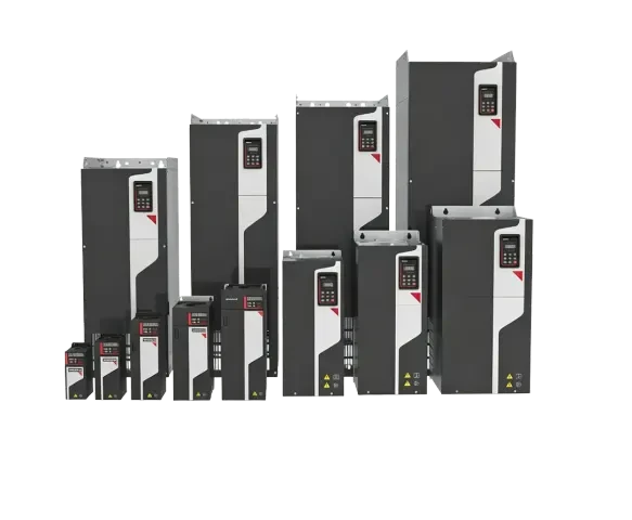
Wolong WD200 Series High-Performance Universal Variable Frequency Drive
Wolong WD200 Series High-Performance General-Purpose Variable Frequency Drives offer power ratings from 0.75 to 1000 kW. They support single-phase 200~240 V, three-phase 200~240 V, three-phase 380~480 V, and three-phase 660~690 V power supplies, driving three-phase asynchronous motors, permanent magnet synchronous motors, and synchronous reluctance motors. Features include V/F control, open-loop vector (SVC), closed-loop vector (FVC), and decoupled voltage-frequency control modes. Speed ranges are 1:200 (SVC) / 1:1000 (FVC). Output torque is 0.5% of rated at 0 Hz and 150% of rated at 200% Hz. Efficiency reaches up to 98%. Supports common DC bus multi-drive and four-quadrant applications.
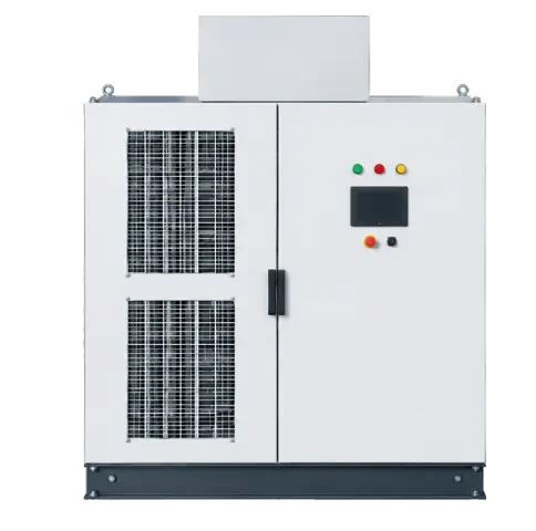
Wolong WD5100 Series Universal High-Voltage Variable Frequency Drive
Series-connected multi-level AC-DC-AC high-to-high configuration. 6kV series capacity: 250~9000 kVA; 10kV series: 250~16000 kVA. Input power factor ≥0.95, input current THD ≤4%. Maximum speed ratio 200:1 (FVC). Compatible with asynchronous motors, electrically excited synchronous machines, and permanent magnet synchronous machines. Widely used for energy saving in fans and pumps, as well as process drives, across oil & gas, power, chemical, metallurgy, building materials, and municipal sectors.
Related Case Studies
All Cases
Mining and Metallurgy
Wolong High-Voltage Variable Frequency Drive Case Study | Pakistan K Electric Power Supply Project | MV VFD System Tendering and Engineering Delivery
Longde Electric (Zhejiang) Power Electronics issues Authorization Letter NO.WLPEFX20260019, authorizing Pakistani agent Techno Control Pvt. Ltd. to bid for the K Electric VFDs project. The project confirms ten delivery commitments—including technical clarification, drawings, protection coordination, interfaces, HVAC dimensions, foundations, signal exchange, software backup, and O&M training—as specified in the Technical Clarification Letter.

Mining and Metallurgy
Wolong WD5100 High-Voltage Variable Frequency Drive Case Study | Saudi CG Test Bench Project | 6560kW Motor Drive VFD Speed Control
The Saudi CG Test Bench Project (CG Saudi Test Bench Project MVC) was commissioned in 2014/6, utilizing 1 units of 6560kW high-voltage variable frequency drives to power large-capacity motor loads. This project represents a flagship overseas deployment of the series-connected multi-level high-voltage VFD solution on the same platform.

Paper Chemicals
Wolong High-Voltage VFD Case Study | German ATB Industrial Project | 2000kW Compressor Variable Frequency Drive
The ATB Germany MVC project went live in 2015/10, utilizing 1 units of 2000kW high-voltage variable frequency drives to power industrial compressors. This represents a landmark achievement for high-voltage VFD solutions entering Europe's premium industrial market.
Cases are automatically linked by product series and application industry, allowing you to view retrofit details and performance data for similar operating conditions.
Looking for a motor and energy-saving solution tailored to your operating conditions?
Submit request. Our technical engineer will contact you within 1 business days.